Giofrelle Pump Station
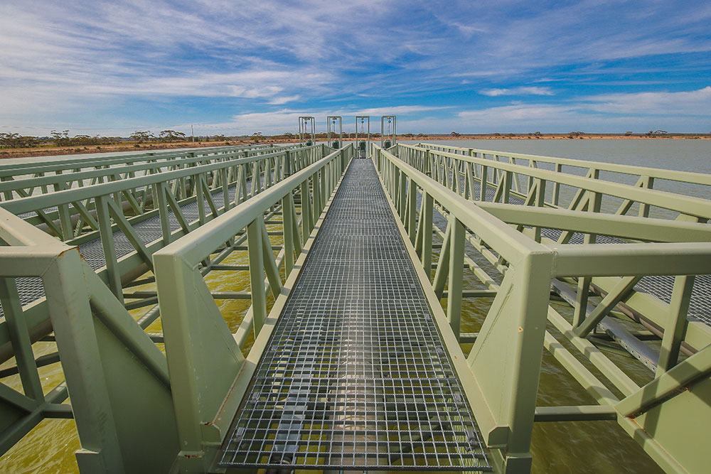
Azzco Engineering were commissioned to design, draft, manufacture and install four 40m long pump station gantry structures. These pump gantry structures were to be supported off the existing pump support structure at the embankment and at the opposite end be supported by floating pontoons to allow the pump station gantry to pivot as the water level falls and rises.
The following provides the approach adopted to produce the Gantry structures:
-
Initial Client Consultation
-
Concept Design for Member Sizing
-
Quotation to produce four off gantry structures
-
Detailed Design
-
3D Modelling and Manufacturing Drawings
-
Manufacture
-
Installation
Client Consultation:
Discussions were initially had with the client to understand the requirements for the project and to review the client inputs for the design of the gantry frame. The client provided a AutoCAD drawing showing an idea on what they were seeking to be developed further, the drawings identified four sections of 10m initially starting with two sections horizontally positioned and the remaining sections positioned at an angle which was to be determined to suit the level of the water.
Once the client drawings were reviewed concept designs were produced to preliminarily size the gantry members so that detailed costings could be provided to fully detail design the gantry, manufacture it and install it on site.
Concept Design:
In order to provide a fully defined scope of works and costings initially a concept design was carried out to size the members of the gantry. Finite Element Analysis was used to identify preliminary member sizes, software used was SpaceGass which checks the members to AS4100.
The following provides the process for undertaking the preliminary member sizes:
-
Modelling of Gantry Frame in SpaceGass
-
Application of Loads to AS1170 and AS1170.2
-
Application of Load Combinations to AS4100 and AS1170
-
Results for Member Capacity and Displacement
The following snapshot provides the SpaceGass Model produced for the preliminary gantry member sizing:

Figure 1 – SpaceGass Model
Quotation for four Gantry Structures:
From the preliminary member sizing a detailed quotation was carried out to provide a cost to detail design, manufacture and install the four gantry structures which included the pontoons, attachment and modifications to the existing pump structure, pump removal trolley system and monorail.
Detailed Design and Drawings:
In order to manufacture the pump gantries and associated equipment detailed design was required. The following details the process to complete the detailed design:
-
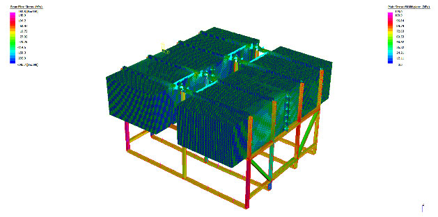
FEA of the Gantry Frame using Strand7 software to model main members and plate connections and stiffeners
-
FEA of the Pontoon and supporting structure using Strand7
-
FEA of the Pump removal trolley and monorail system using Strand7
-
Verification of the existing pump support structure to support the new gantry frames using SpaceGass.
-
Detailed design was carried out to AS4100 (Structural Members), AS3990 for Plate and Stiffener connections, AS1418 for monorail design.

Figure 2 – Example FEA - Pontoon FEA Analysis – Stress Plots (Beams and Plates)
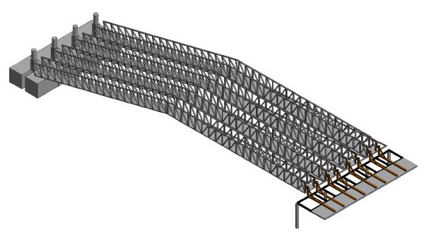
Once the detailed design was completed 3D modelling software was used to model up the gantry structures, pontoons, pump trolley and monorail and modifications necessary to support the new gantry structures at the existing pump structure.

Figure 3 – 3D Model of Gantry Frames
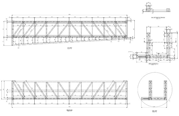
Manufacturing drawings were then produced for each gantry frame section and associated equipment.

Figure 4 – Example Manufacturing Drawing


